

In addition to new preamplifier module I would like to present dedicated power supply. This simple module have both anode and heater rails regulated and stabilised. Anode regulator is based on discrete components.
Dimensions: 100 x 60 mm
Uncompromising quality at an affordable price
In addition to new preamplifier module I would like to present dedicated power supply. This simple module have both anode and heater rails regulated and stabilised. Anode regulator is based on discrete components.
Dimensions: 100 x 60 mm
In addition to my „Fully Tube, regulated HV Anode Power Supply” i have created second PCB which is additional regulated power supply to cover heater of powered tubes. Board is exactly half of my „Highly integrated supply for Tube Preamplifiers”, adjusted to control relay.

Created to provide complete solution for powering tube preamplifiers and make it fully regulated.

Heater power supply is based on integrated LDO and is capable to deliver up to 5A. Voltage at its output rises slowly from 1,2V to desired voltage in 10s to protect tube heaters from current surge when they are cool. Output voltage selection can be done in 2 ways:

Bridge rectifier in this circuit is created from 10A Schottky diodes to provide low voltage drop at the input. All this circuit is preceded with CLC smoothing circuit for best noise performance.
Heater supplying voltage is balanced and elevated comparing to anode supply GND by 1/4 of anode voltage. This feature is helpful in circuit when cathodes of tubes are biased by high voltage for example: SRPP, White Cathode Followers, Mu Followers.

The last part of the board is control unit. This circuit contains two part: anode delay circuit and audio muting circuit. Timing is set to 30s delay of anode voltage and 40s for audio mute. Timers as well as relay output are powered by third, 5V regulator. Thanks to this initial delay it is stable in every condition and relay is always powered from stable voltage.
This power supply is complete solution for tube pre- and amplifiers – simple and complex as well. It is based on semiconductors and contains both: anode and heater stabilised power supply.

Maybe you will be surprised, but most of this unit is made of SMD components. Only some critical parts are THT – power, and capacitors.

Circuit is designed to meet even most extreme requirements. Could be used to power simple single tube preamplifier and extreme balanced tube preamplifier with differential amplifier and 4x White Cathode followers created with 6N30P tubes. In addition, it is possible to power small amplifiers for example: stereo EL84 SE Amp, or single channel EL84 PP Amp.

Single PCB contains:
Anode power supply is built over discrete high voltage regulator similar to my V3.1 regulators. This means that this regulator is completely discrete, based upon SMD components, specially selected to operate with voltages up to 400V. Output voltage is set by potentiometer or could be set by fixed resistor.
Anode regulator is preceded by CRC smoothing filter for best noise performance and also to increase overall PSRR.
Heater power supply is based on integrated LDO and is capable to deliver up to 5A. Voltage at its output rises slowly from 1,2V to desired voltage in 10s to protect tube heaters from current surge when they are cool. Output voltage selection can be done in 2 ways:
Bridge rectifier in this circuit is created from 10A Schottky diodes to provide low voltage drop at the input. All this circuit is preceded with CLC smoothing circuit for best noise performance.
Heater supplying voltage is balanced and elevated comparing to anode supply GND by 1/4 of anode voltage. This feature is helpful in circuit when cathodes of tubes are biased by high voltage for example: SRPP, White Cathode Followers, Mu Followers.
The last part of the board is control unit. This circuit contains two part: anode delay circuit and audio muting circuit. Timing is set to 30s delay of anode voltage and 40s for audio mute. Timers as well as relay output are powered by third, 5V regulator. Thanks to this initial delay it is stable in every condition and relay is always powered from stable voltage.

Best thermal performance is achieved by good thermal design. This supply is able to dissipate a lot of power.
And in addition all this things were achieved in dimensions: 100 x 100 x 50mm!!
Enjoy. 😉
Big success of V3.1 regulator shows me that this topology has a huge potential to implement in many applications. For those who uses my V3.1 regulator to create its standalone power supply I have got something interesting! V2.0 power supply which is better and stronger implementation of V3.1 topology.
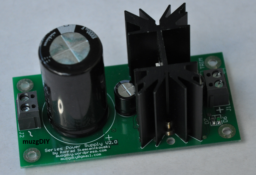
Better means 3 more current sources which replace resistors. This give us better PSRR, more gain in error amplifier and better immunity to output current ripple.
Stronger means that is equipped with powerful TO220 transistor on dedicated heatsink. This gives me possibility to increase output current up to 3A!
But this is not the end! At the input, after rectifier and smoothing capacitor there is LC pi filter based on Common Mode inductor. Such filter could help to block disturbances which are coming from mains and passes transformer. It is also working in opposite way and blocks disturbances from supplied circuit and not allow them to pass to the transformer.
The PCB of this power supply was created in such a way that helps to remove heat from heatsink. Beneath it there are many holes which in shortest way cool it down.
Dimensions: 45 x 90 mm, high 50 mm
Shunt power supplies always are not so simple in use as series but all shunt fans knows, that this effort will pay of. And for that people’s I have got something special. New power supply with high current capability. Input CCS can be set up to 1000mA!
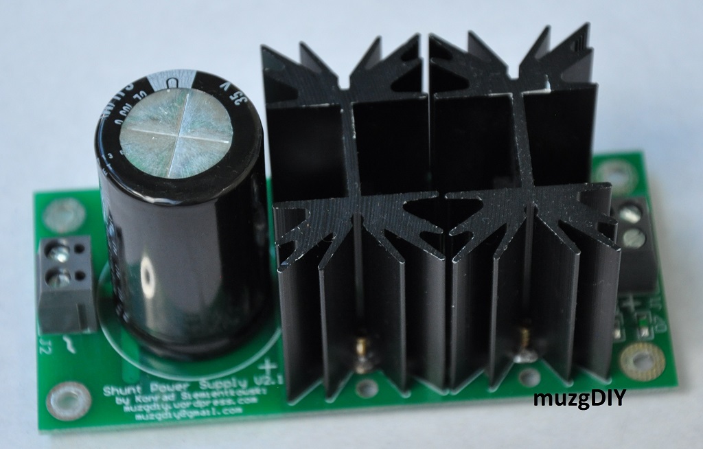
For everyone who would like to say that it is Salas I want to say: you are wrong! It is my proprietary, bipolar design, similar to V8.0 regulator and taking best from both – V3.1 and V8.0 regulators.
Designed in the way that can be used instead of popular „S” power supplies or even replace it in ready designs. Comparing to its famous competitor:
– requires less voltage drop across regulator – typically 1,5V
– is more flexible – from few up to 1000mA BIAS current
– output voltage can be set from 3 to 15V by fixed resistor or helipot.
– very stable output voltage during warming – no more worry about your circuit!
– stable output voltage in function of output current – no more worry about your circuit!
– CLC input filter to block noise in both ways
From user experience I can guarantee that performance and sound is similar or even better.
Today I would like to show You one of my bipolar power supplies. It is based on same topology like in V3.X series but with cascade bias constant current source and with CCS in Vref. 

Board are very compact. Only few largest component are located at top side of PCB – rest are in SMD on bottom side.

Shape of the board, dimensions and mounting holes positions are the same like in rest of my bipolar power supplies so can be swapped for choosing the best for us.
Dimensions of PCB: 60 x 82mm
Integrated constant current sources and voltage reference circuit consist 12 LED’s so board emits light also. Output voltage is set by feedback voltage divider mounted on board – should be set during assembling.
To use this power supply You must provide only 2 x AC voltage to connectors one one edge of PCB. Here You can find example of use with my transformer board:

Maximal output Current: 500mA @15V
Maximal Power dissipation: 2W/channel
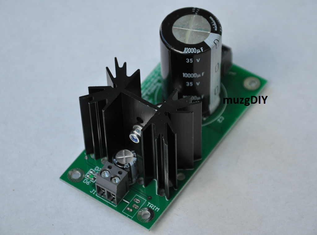
Today I would like to show You my strongest from single power supply board. It is based on TEZ16 transformer, Schottky bridge with 3A diodes and V3.1 regulator with high bias current:


Maximal output current: 1100mA @5V (@225Vac)
After 1hour operating with 1100mA (5V) at 27 Celsius degree of ambient temp, heat sink temperature rises 57 Celsius degree.
Till today (24 April 2015) I have designed 14 versions of voltage regulators of which as many as 9 are newly and my own topologies. I know You could have a problem to choose a right one for Your application, so I would like to explain You differences between all versions.

In general there are 3 groups.
In explanation:
All deigns (excluding V3.0max) are made on 30mm x 15mm PCBs like this:

Pinout always are:
so they can replace integrated regulators like 78XX or discrete like TPA Trident Shunt.
You can use only 3 center pins for replacement of 78XX, or all 5 pins when board is designed to use my discrete regulators.
For better heat dissipation external heatsink can be used. I use Fisher heatsinks mounted by 3M heat-conductive tape:

This tape can be also used to stick the regulator to any metal elements of Your device. Here You can find V1.0 regulators mounted on Revox B226 CD to provide better opamp supply:

For detailed information about specific version please choose right one from menu. Not all version are carefully described on my page.
Transformer board designed to use with TEZ10 and TEZ16 transformers. This one has 2 x 15V 500mA.


Can be used with my universal preamplifier module and bipolar power supplies.
Dimensions: 60mm x 70mm, 48mm heigh.
Today I would like to show You my new power supply based on 6VA Breve transformer, and my discrete voltage regulator V3.1. Of course any other of my 3 pin regulators can be used. This power supply is dedicated to supply USB1.1 and USB2.0 audio DACs and converters.
This one is set to 5V and in assumption should deliver at least 500mA of current.


After measurement, power supply from 230V of AC voltage can deliver 5V up to 550mA of current.
After 8h of operating in 24,5 C ambient temperature with 5V 500mA active load, temperature of heatsink reached 58,5C.
Due to voltage drift in temperature output voltage drops from 5,11V to 4,9V.
Parameters:
– input voltage: 230V 50Hz
– output voltage: 5V
– maximal output current: 500mA
– maximal output power: 2,5W
– dimensions: 50mm x 75mm, 45mm height
