Today I put schematics of all tube stuff that I have presented on my website. All circuits are checked and tested. Enjoy and have fun in evaluating. Order of bare PCB is possible via email or http://www.muzgaudio.com
Dzisiaj zamieściłem schematy do wszystkich lampowych układów prezentowanych na mojej stronie. Wszystkie układy zostały zbudowane i sprawdzone. Życzę dużo zabawy w budowaniu tych układów. Istnieje także możliwość zamówienia pustej płytki PCB poprzez email lub stronę http://www.muzgaudio.com.
In addition to new preamplifier module I would like to present dedicated power supply. This simple module have both anode and heater rails regulated and stabilised. Anode regulator is based on discrete components.
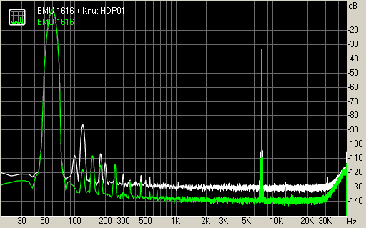
Presented preamplifier is one of my line preamplifier with low gain (up to ~10x) designed to be used with ECC82 and 6N30P tubes. First stage is responsible for voltage amplification (VAS) and is based on SRPP topology. Second stage is cathode follower which isolates VAS from output load and provide less than 100R output impedance. This combination gives us wide frequency response and can easily drive any load even 300R headphones.
Parameters:
Frequency response: 2Hz – 1.35MHz to 47k load (2.2uF output capacitor)
Amplification factor: base 10V/V (20dB)
Anode supply: 300V 60mA
Heater supply: 6,3V 1500mA
Output impedance: ~100R
Additional features:
input resistor divider for gain reduction to desired one
place for bypass capacitor on cathode resistor of SRPP circuit to increase gain
muting relay at the output
possibility to change heater style from ECC88 like tubes to ECC82 like tubes in SRPP circuit
Instead of expensive 6N30P, cheaper 6N6P could be used. This has influence on output impedance and linearity of circuit (more THD). Further price reduction can be achieved by replacing ECC82 with 6N1P (this modification should be preceded by changing cathode resistor) what gives the same side effect.
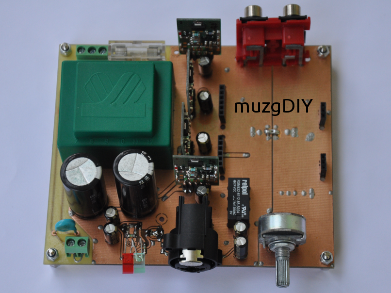
This power supply is complete solution for tube pre- and amplifiers – simple and complex as well. It is based on semiconductors and contains both: anode and heater stabilised power supply.
Maybe you will be surprised, but most of this unit is made of SMD components. Only some critical parts are THT – power, and capacitors.
Circuit is designed to meet even most extreme requirements. Could be used to power simple single tube preamplifier and extreme balanced tube preamplifier with differential amplifier and 4x White Cathode followers created with 6N30P tubes. In addition, it is possible to power small amplifiers for example: stereo EL84 SE Amp, or single channel EL84 PP Amp.
Single PCB contains:
Anode high voltage, regulated power supply 150-350V 200mA with delayed on,
Heater regulated power supply 1,2-12,6V 5A with slow ramp,
Mute delay circuit to control audio output relay – enable output of preamplifier few second after anode supply is activated
Anode power supply is built over discrete high voltage regulator similar to my V3.1 regulators. This means that this regulator is completely discrete, based upon SMD components, specially selected to operate with voltages up to 400V. Output voltage is set by potentiometer or could be set by fixed resistor.
Anode regulator is preceded by CRC smoothing filter for best noise performance and also to increase overall PSRR.
Heater power supply is based on integrated LDO and is capable to deliver up to 5A. Voltage at its output rises slowly from 1,2V to desired voltage in 10s to protect tube heaters from current surge when they are cool. Output voltage selection can be done in 2 ways:
by jumper in predefined steps: 6,3V; 7V; 12,6V
by variable potentiometer in range 1,2 – 13V (could be more)
Bridge rectifier in this circuit is created from 10A Schottky diodes to provide low voltage drop at the input. All this circuit is preceded with CLC smoothing circuit for best noise performance.
Heater supplying voltage is balanced and elevated comparing to anode supply GND by 1/4 of anode voltage. This feature is helpful in circuit when cathodes of tubes are biased by high voltage for example: SRPP, White Cathode Followers, Mu Followers.
The last part of the board is control unit. This circuit contains two part: anode delay circuit and audio muting circuit. Timing is set to 30s delay of anode voltage and 40s for audio mute. Timers as well as relay output are powered by third, 5V regulator. Thanks to this initial delay it is stable in every condition and relay is always powered from stable voltage.
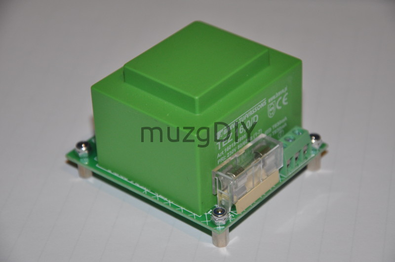
Best thermal performance is achieved by good thermal design. This supply is able to dissipate a lot of power.
And in addition all this things were achieved in dimensions: 100 x 100 x 50mm!!
Big success of V3.1 regulator shows me that this topology has a huge potential to implement in many applications. For those who uses my V3.1 regulator to create its standalone power supply I have got something interesting! V2.0 power supply which is better and stronger implementation of V3.1 topology.
Better means 3 more current sources which replace resistors. This give us better PSRR, more gain in error amplifier and better immunity to output current ripple.
Stronger means that is equipped with powerful TO220 transistor on dedicated heatsink. This gives me possibility to increase output current up to 3A!
But this is not the end! At the input, after rectifier and smoothing capacitor there is LC pi filter based on Common Mode inductor. Such filter could help to block disturbances which are coming from mains and passes transformer. It is also working in opposite way and blocks disturbances from supplied circuit and not allow them to pass to the transformer.
The PCB of this power supply was created in such a way that helps to remove heat from heatsink. Beneath it there are many holes which in shortest way cool it down.
but now project is unavailable, maybe cause of instability of original design.
Input circuit is pair of JFET (I’m using 2SK246BL/J103BL). Current from input was mirrored in bipolar current mirror, and directly connected to bipolar MOSFET source follower. Circuit is using current feedback loop.
My first implementation of this amplifier is quite big, but sound quality is amazing!
I would like to show you my simple opamp preamplifier.
Board are very universal. Can be configured as:
Stereo, non-inverting preamplifier
Stereo, inverting preamplifier
Stereo, differential amplifier
Mono, balanced in – balanced out preamplifier (like input section of instrumentation amplifier)
Mono, SE input – balanced output
Both inputs are balanced but can be set as SE by simply connecting one phase to ground.
All single operational amplifiers can be used. LT1028/LT1115, AD797, OPA627, NE5534, OPA134/604, LME49710, LME49990 with adapter and similar.
Power supply are based on 2 diode bridges and V3.0max discrete series regulators so board can be powered directly from 2 x 15V transformer with separated windings.
I have designed dedicated transformer board for this preamplifier: