Hot and powerful! – V2.1 Shunt Power Supply

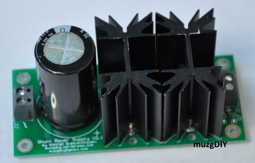
Shunt power supplies always are not so simple in use as series but all shunt fans knows, that this effort will pay of. And for that people’s I have got something special. New power supply with high current capability. Input CCS can be set up to 1000mA!

DSC_0426

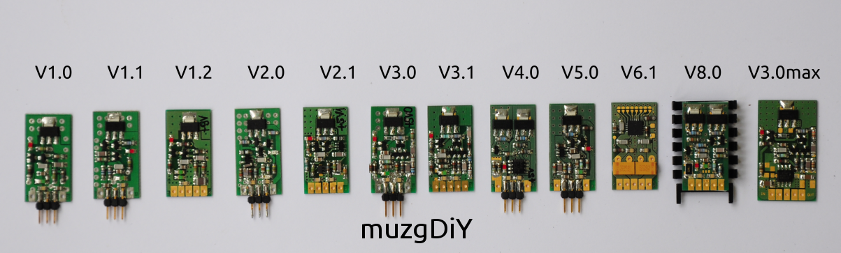
For everyone who would like to say that it is Salas I want to say: you are wrong! It is my proprietary, bipolar design, similar to V8.0 regulator and taking best from both – V3.1 and V8.0 regulators.

Designed in the way that can be used instead of popular „S” power supplies or even replace it in ready designs. Comparing to its famous competitor:

– requires less voltage drop across regulator – typically 1,5V

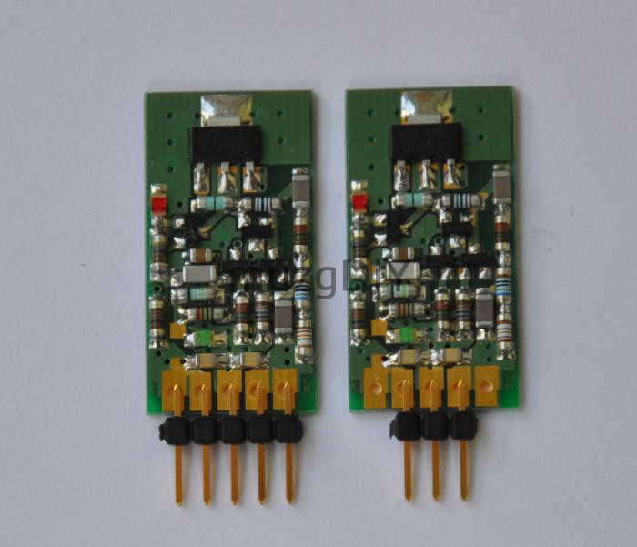
– is more flexible  – from few up to 1000mA BIAS current
– output voltage can be set from 3 to 15V by fixed resistor or helipot.

– very stable output voltage during warming – no more worry about your circuit!

– stable output voltage in function of output current – no more worry about your circuit!

– CLC input filter to block noise in both ways

From user experience I can guarantee that performance and sound is similar or even better.

New in Family – V9.0 Shunt Regulator

After long break from designing new voltage regulator topologies I decided to create some shunt regulator with opamp based error amplifier.

Like all my shunt regulator this one is also uses Shiklai based current source at the input but rest of design is totally different but it is nothing new on the market. Similar topology is used in TPA Trident regulator and Tent Regulator but it not has a disadvantages of the first one. Output voltages not varies from input voltage and is stable in every load condition.

Current can be set up to 100mA!

Specially designed to power precision audio components like: DACs, ADCs, S/PDIF receivers, clock circuits.

Voltage reference based on LED diode to ensure low noise. There are possibility to use precision voltage reference instead of LED diode for good voltage precision and temperature stability.

Simply decoupling circuit on regulator PCB is sufficient to ensure stability of regulator but external high capacity can be connected to provide low ripple with high speed output current change.

Dropout voltage is at least 1,5V, but I recomend values from 2V to 3V. You must calculate this for power dissipation max. 1W.

Pinout compatible with standard LM78XX regulators like LM7805 and similar. If LM78XX regulator will be replaced by V8.0 only 3 central pins can be used. If board is developed specially for V8.0 all 5 pin can be used.

Dimensions are always the same: 30mm x 15mm.

VX.X – Voltage Regulators versions explanation

Till today (24 April 2015) I have designed 14 versions of voltage regulators of which as many as 9 are newly and my own topologies. I know You could have a problem to choose a right one for Your application, so I would like to explain You differences between all versions.

All_3pin

In general there are 3 groups.

  •  discrete series regulators
  •  discrete shunt regulators
  •  integrated regulators (series)

In explanation:

  • V1.0 – simple series regulator with NPN output, single transistor error amplifier, LED voltage reference and CSS bias    circuit.

  • V1.1 – simple series regulator with Szikai output, single transistor error amplifier, LED voltage reference and CSS bias circuit.

  • V1.2 – V1.0 with some improvement for high output voltage, gold plated PCBs.

  • V2.0 – series regulator with opamp error amplifier, Szikai output, LED voltage reference and CCS bias circuit.

  • V2.1 – series regulator with opamp error amplifier, NPN output, LED voltage reference and CCS bias circuit, gold plated PCBs.

  • V3.0 – series regulator with transistor differential amplifier, NPN output, LED voltage reference, CCS bias circuit.

  • V3.1 – V3.0 with some improvements for better soldering, precision voltage reference, precision output voltage set, gold plated PCBs.

  • V3.0max – V3.0 with improvements for high output voltage, gold plated PCBs.

  • V4.0 – shunt regulator based on TL431 with Sziklai CCS, gold plated PCBs.

  • V5.0 – series regulator with opamp error amplifier in shunt configuraton, gold plated PCBs.

  • V6.1 – series regulator based on Texas Instruments TPS7A4700/3301, gold plated PCBs.

  • V8.0 – shunt regulator with transistor differential amplifier, Sziklai CCS, precision/LED voltage reference, gold plated PCBs.

All deigns (excluding V3.0max) are made on 30mm x 15mm PCBs like this:

V3X_35pin_1

Pinout always are:

  1.  IN
  2.  IN
  3.  GND
  4.  OUT
  5.  OUT

so they can replace integrated regulators like 78XX or discrete like TPA Trident Shunt.

You can use only 3 center pins for replacement of 78XX, or all 5 pins when board is designed to use my discrete regulators.

For better heat dissipation external heatsink can be used. I use Fisher heatsinks mounted by 3M heat-conductive tape:

V8_heatsink_1

This tape can be also used to stick the regulator to any metal elements of Your device. Here You can find V1.0 regulators mounted on Revox B226 CD to provide better opamp supply:

V1_heatsink_3

For detailed information about specific version please choose right one from menu. Not all version are carefully described on my page.

Hot and naked – V8.0 discrete Shunt Regulator

Today I have something for Shunt Regulator fans – V8.0 Shunt Regulator!

V8_overview_1

Based on V3.X error amplifier design, with LED biased, Sziklai Constant Current Source.

Current can be set up to 100mA!

I recommend to use it with dedicated heatsink because Shunt Regulators always dissipate power.

V8_heatsink_1

Specially designed to power precision audio components like: DACs, ADCs, S/PDIF receivers, clock circuits.

Output voltage can be set by components in negative feedback circuit from 1V2 to 9V eg. : 1V2, 2V5, 3V3, 5V, 6V, 8V, 9V. Transistor circuit allows to build version for negative voltage.

Voltage reference based on LED diode to ensure low noise. There are possibility to use precision voltage reference instead of LED diode for good voltage precision and temperature stability.

Simply decoupling circuit on regulator PCB is sufficient to ensure stability of regulator but external high capacity can be connected to provide low ripple with high speed output current change.

Dropout voltage is at least 1,5V, but I recomend values from 2V to 3V. You must calculate this for power dissipation max. 1W.

Pinout compatible with standard LM78XX regulators like LM7805 and similar. If LM78XX regulator will be replaced by V8.0 only 3 central pins can be used. If board is developed specially for V8.0 all 5 pin can be used.

Dimensions are always the same: 30mm x 15mm.

Create a website or blog at WordPress.com

Up ↑