Better and stronger – V2.0 Series Power Supply

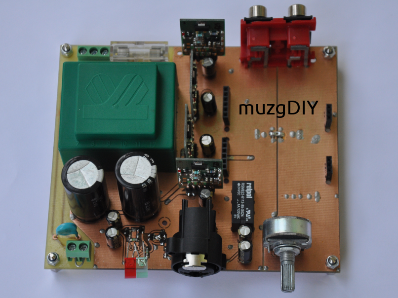
Big success of V3.1 regulator shows me that this topology has a huge potential to implement in many applications. For those who uses my V3.1 regulator to create its standalone power supply I have got something interesting! V2.0 power supply which is better and stronger implementation of V3.1 topology.

Supply_V20_front

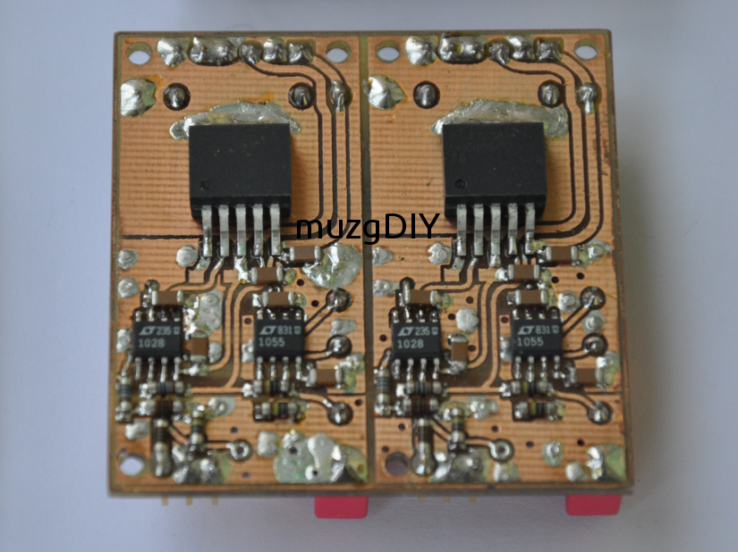
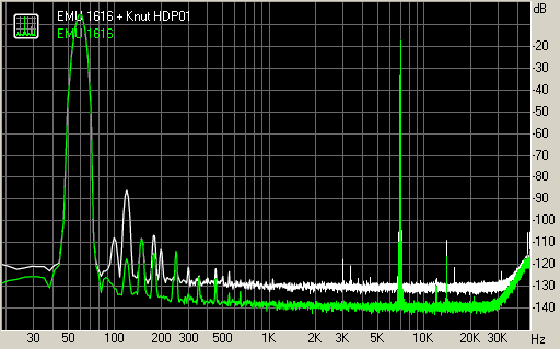
Better means 3 more current sources which replace resistors. This give us better PSRR, more gain in error amplifier and better immunity to output current ripple.

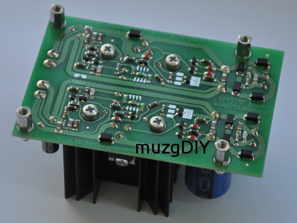
Stronger means that is equipped with powerful TO220 transistor on dedicated heatsink. This gives me possibility to increase output current up to 3A!

Supply_V20_output

But this is not the end! At the input, after rectifier and smoothing capacitor there is LC pi filter based on Common Mode inductor. Such filter could help to block disturbances which are coming from mains and passes transformer. It is also working in opposite way and blocks disturbances from supplied circuit and not allow them to pass to the transformer.

The PCB of this power supply was created in such a way that helps to remove heat from heatsink. Beneath it there are many holes which in shortest way cool it down.

Dimensions: 45 x 90 mm, high 50 mm

Simple but Flexible – V1.2 series regulator

Welcome after a long break from writing!

Today I would like to show You one of my oldest design of series voltage regulator. V1.2 is exactly V1.0 with greater reference voltage and lot of space for output capacitor. It is also produced on gold plated PCB’s.

V12_front_1

V1.2 is constant current sourced biased regulator. It is closed loop device with error amplifier based on single transistor. Voltage reference is done by 2 LEDs. Only transistor/diode design allows to make positive and negative versions of this regulator.

This design is mostly used by my to supply analog circuits with voltages +/-12V and +/-15V. It is also good choice as voltage pre-regulator before accurate and fast V3.1 and V2.1 designs. I use it as output regulator of clock power supply:

Clock_supply_1_1

Discrete Bipolar Power Supply V1.2

Today I would like to show You one of my bipolar power supplies. It is based on same topology like in V3.X series but with cascade bias constant current source and with CCS in Vref. Discrete_1

Discrete_2

Board are very compact. Only few largest component are located at top side of PCB – rest are in SMD on bottom side.

Discrete_3

Shape of the board, dimensions and mounting holes positions are the same like in rest of my bipolar power supplies so can be swapped for choosing the best for us.

Dimensions of PCB: 60 x 82mm

Integrated constant current sources and voltage reference  circuit consist 12 LED’s so board emits light also. Output voltage is set by feedback voltage divider mounted on board – should be set during assembling.

To use this power supply You must provide only 2 x AC voltage to connectors one one edge of PCB. Here You can find example of use with my transformer board:

Discrete_4

Maximal output Current: 500mA @15V

Maximal Power dissipation: 2W/channel

Headphone Protection V2.1

Today I would like to show You my protection circuit.

This circuit is designed to do few functions:

– delay at startup – few seconds set by RC

– DC protection

– AC interruption detection for cancelling pops after switching off device.

Circuit are fully discrete and it is my own design. Also circuit has built-in LED indicator.

Output OK:

Prot_OK1

Output Not OK,or during start-up delay:

Prot_NOK1

Dimensions of board: 50mm x 50mm.

TPA6120 + LT1028 for HeadFun

Next amplifier for HeadFun is based on TPA6120 TI current feedback, high current, operational amplifier + Linear LT1028 for input buffer/voltage amplification. TPA6120 needs input buffer on non-inverting input due to ~6uA of current sourcing from this pin.

HeadFun_TPA6120_1

LME49600 + LT1028 for HeadFun

Next headphone amplifier module designed to use witch HeadFun mainboard is based on LME49600/610 TI buffer witch LT1028 voltage amplifier and LT1055 DC servo.

HeadFun_LME49600_1

Electrolytic and DC servo capacitors are mounted at bottom side of PCB. I really like this combination of opamps. LT1028 and AD797 are my favourite opamps for voltage amplification. LT1055 has very good performance in DC servos cause of low input current and low current noise. This combined with big values of resistors at input gives good noise performance.

Feedback loop is voltage type. Voltage amplification is set to 10x.

HDP01 Discrete for HeadFun

Design based on corrected and improved schematic originaly posted by Knut Harald Nygaard on his home page:

http://www.andiha.no/index.html

but now project is unavailable, maybe cause of instability of original design.

Input circuit is pair of JFET (I’m using 2SK246BL/J103BL). Current from input was mirrored in bipolar current mirror, and directly connected to bipolar MOSFET source follower. Circuit is using current feedback loop.

My first implementation of this amplifier is quite big, but sound quality is amazing!

https://picasaweb.google.com/muzg123/CFAHeadampHDP01

My second implementation is module for HeadFun amplifier made from SMD components (excluding electrolytic caps and JFETs) and PCB as heatsink:

HeadFun_HDP01_1

Not only sound quality of HDP01 is incredible. Measurements also shows good result:

THD+N 1kHz -3dB output level (referenced to input level of EMU1616), load 270R:

THD+N

IMD+N with the same conditions:

IMD+N

Results in RMAA:

Wyniki_RMAA

Finally, till now this is the best sounding headphone amplifier that I ever heard! I’m using it with Sennheiser HD580 headphones.

HeadFun – Modular Headphone Amplifier

Today I want show You my modular Headphone Amplifier design. I want to test best headphone amplifier circuit in my DAC, so I decided to make it modular. When I  designed 4 different modules but whole DAC is still not completed, I decide to make motherboard that creates complete and safe in use headphone amplifier. Additional RCA output allows use it as preamplifier.

Whole amplifier has modular design. Motherboard contains:

  • 10/16VA Power supply
  • 4 piece of my voltage regulator (dedicated is V3.0max)
  • volume control eg. ladder like in photo
  • output protection circuit with AC voltage interruption detection and delayed ON
  • set of input/output connectors
  • amplifier modules socket

So You can freely replace regulators and amplifier modules.

Here is complete amplifier with V3.0max regulators and HDP01 current feedback amplifier:

HeadFun_Complete_Front

Board at night:

HeadFun_Complete_Night

Please choose the right module from menu for detailed description.

Till today I have done 5 different amplifier modules:

1. HDP01 discrete current feedback amplifier

2. Bipolar, discrete, current feedback amplifier with MOSFET output

3. LME49600 + LT1028 + servo LT1055

4. TPA6120 + LT1028

5. LT1028 + discrete, bipolar output buffer

Motherboard for HeadFun

Motherboard contains:

  • 10/16VA Power supply
  • 4 piece of my voltage regulator (dedicated is V3.0max)
  • volume control eg. ladder like in photo
  • output protection circuit with AC voltage interruption detection and delayed ON
  • set of input/output connectors
  • amplifier modules socket

So You can freely replace regulators and amplifier modules.

HeadFun_Motherboard_Front

Create a website or blog at WordPress.com

Up ↑