Hybrid tube preamplifier is module containing SRPP tube voltage stage and CCS biased source follower based on high voltage MOSFET transistor. CCS is fully discrete bipolar. Both transistors are placed on powerful heatsink.
First stage is the same as in both my fully tube preamplifiers (with cathode follower and White cathode follower) but only difference is that here expensive 6N30P tubes are replaced by more modern components like transistors.
Most of components are SMD type. Only few bigest components are THT. Tubes are mounted on bottom side of PCB to helps
Parameters:
Frequency response: 2Hz – 1.35MHz to 47k load (2.2uF output capacitor
Amplification factor: base 10V/V (20dB
Anode supply: 300V 60mA
Heater supply: 6,3V 700mA
Output impedance: ~100R
Board dimensions: 100 x 100mm
Additional features:
input resistor divider for gain reduction to desired one
place for bypass capacitor on cathode resistor of SRPP circuit to increase gain
muting relay at the output (required external control circuit)
possibility to change heater style from ECC88 like tubes to ECC82 like tubes
This power supply is complete solution for tube pre- and amplifiers – simple and complex as well. It is based on semiconductors and contains both: anode and heater stabilised power supply.
Maybe you will be surprised, but most of this unit is made of SMD components. Only some critical parts are THT – power, and capacitors.
Circuit is designed to meet even most extreme requirements. Could be used to power simple single tube preamplifier and extreme balanced tube preamplifier with differential amplifier and 4x White Cathode followers created with 6N30P tubes. In addition, it is possible to power small amplifiers for example: stereo EL84 SE Amp, or single channel EL84 PP Amp.
Single PCB contains:
Anode high voltage, regulated power supply 150-350V 200mA with delayed on,
Heater regulated power supply 1,2-12,6V 5A with slow ramp,
Mute delay circuit to control audio output relay – enable output of preamplifier few second after anode supply is activated
Anode power supply is built over discrete high voltage regulator similar to my V3.1 regulators. This means that this regulator is completely discrete, based upon SMD components, specially selected to operate with voltages up to 400V. Output voltage is set by potentiometer or could be set by fixed resistor.
Anode regulator is preceded by CRC smoothing filter for best noise performance and also to increase overall PSRR.
Heater power supply is based on integrated LDO and is capable to deliver up to 5A. Voltage at its output rises slowly from 1,2V to desired voltage in 10s to protect tube heaters from current surge when they are cool. Output voltage selection can be done in 2 ways:
by jumper in predefined steps: 6,3V; 7V; 12,6V
by variable potentiometer in range 1,2 – 13V (could be more)
Bridge rectifier in this circuit is created from 10A Schottky diodes to provide low voltage drop at the input. All this circuit is preceded with CLC smoothing circuit for best noise performance.
Heater supplying voltage is balanced and elevated comparing to anode supply GND by 1/4 of anode voltage. This feature is helpful in circuit when cathodes of tubes are biased by high voltage for example: SRPP, White Cathode Followers, Mu Followers.
The last part of the board is control unit. This circuit contains two part: anode delay circuit and audio muting circuit. Timing is set to 30s delay of anode voltage and 40s for audio mute. Timers as well as relay output are powered by third, 5V regulator. Thanks to this initial delay it is stable in every condition and relay is always powered from stable voltage.
Best thermal performance is achieved by good thermal design. This supply is able to dissipate a lot of power.
And in addition all this things were achieved in dimensions: 100 x 100 x 50mm!!
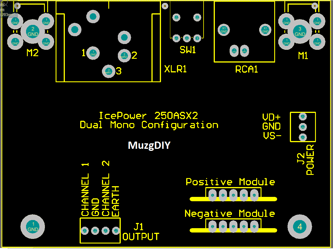
After success with my simple input stage in feeding IcePower Amplifiers with signal I decided to design new, complex input stage with XLR/RCA input and differential output.
Module has fully differential architecture with 2 pcs. of single op-amp at the input and differential amplifier OPA1632 at the output. I’m using DIP8 op-amps at the front to allow user to modify sound to its own preferences. Anyway OPA134 is a good choice for class D users (like IcePower) due to its warm Sound generated by FET input circuit.
Switch between XLR and RCA connector is used to choose right input.
Switch located at the centre of the board is used to select the gain which will be applied to the input signal. Differential gain is selectable between -6dB to 6dB in four steps.
Gain: -6dB to 6dB Imput impedance: 100kΩ Output impedance: 50Ω Frequency response (-3dB): 300kHz limited by RC filter Power supply: +/-12 – 24V (eg. Directly from IcePower module) Power cunsumption: 100mA with OPA134 Dimensions: 80 x 60 x 35mm
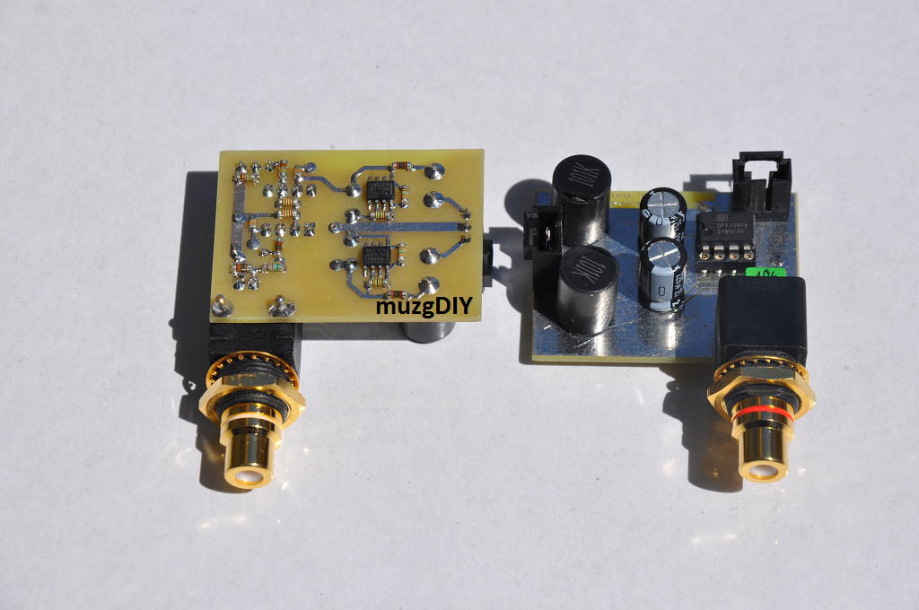
Next project that I would like to show is an input stage for Class D IcePower 500ASP amplifier from B&O with RCA input.
Module is simple to use, non inverting amplifier, based on opamp. Amplification of module is set to 2x to compensate gain loss when SE signal is applied to IcePower board.
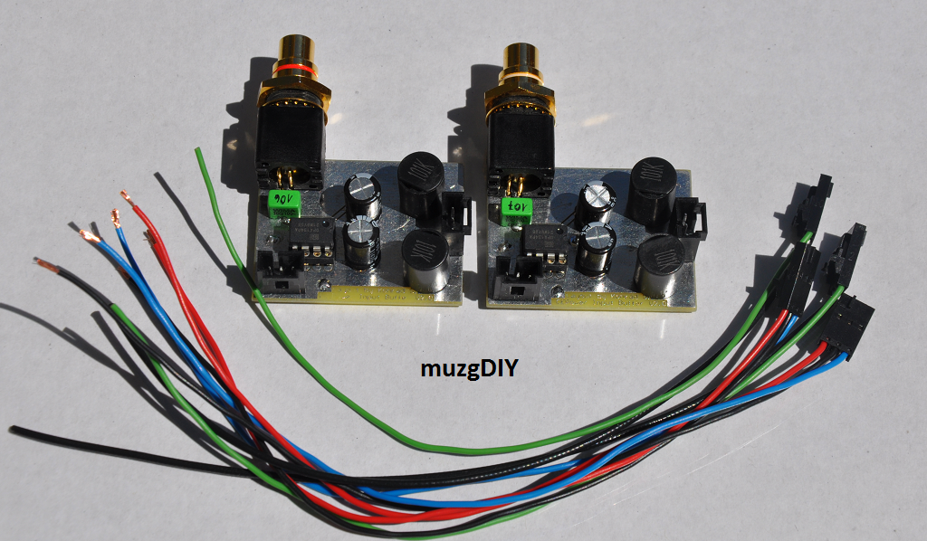
To install module just connect it with 6 cables with IcePower board and it works. No additional components are needed. Module can be powered directly from +/-12V output from IcePower board.
Gain: 2V/V
Imput impedance: 100kΩ
Output impedance: 50Ω
Frequency response (-3dB): 300kHz limited by RC filter
Power supply: +/-12 – 15V (eg. Directly from IcePower module)
Power cunsumption: <50mA with OPA134
Dimensions: 35mm x 46mm
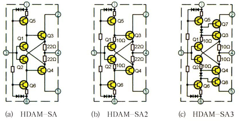
Today I would like to show You tiny Diamond Buffer module designed by my friend Krzysztof. Modules are based on topology used by Marantz in HDAM-SA2, but at this time with different components..
Topology is same like in HDAM-SA2:
Pinout:
1. VSS
2. VSS
3. OUT
4. IN
5. VCC
6. VCC
Modules are very tinny. Dimensions are 20mm x 20mm.
It can be used as audio buffers or input section of current feedback amplifiers.